x


Master Thesis, 2019
Authors: A. Foltman, F. Bielicki, J. N. Dackiw, S. Garivani
Faculty: A. Dubor, A. Sollazzo, R. Krenmueller, J. S. Lara, D. Serrano, M. Zwierzycki
Authors: A. Foltman, F. Bielicki, J. N. Dackiw, S. Garivani
Faculty: A. Dubor, A. Sollazzo, R. Krenmueller, J. S. Lara, D. Serrano, M. Zwierzycki
Introduction
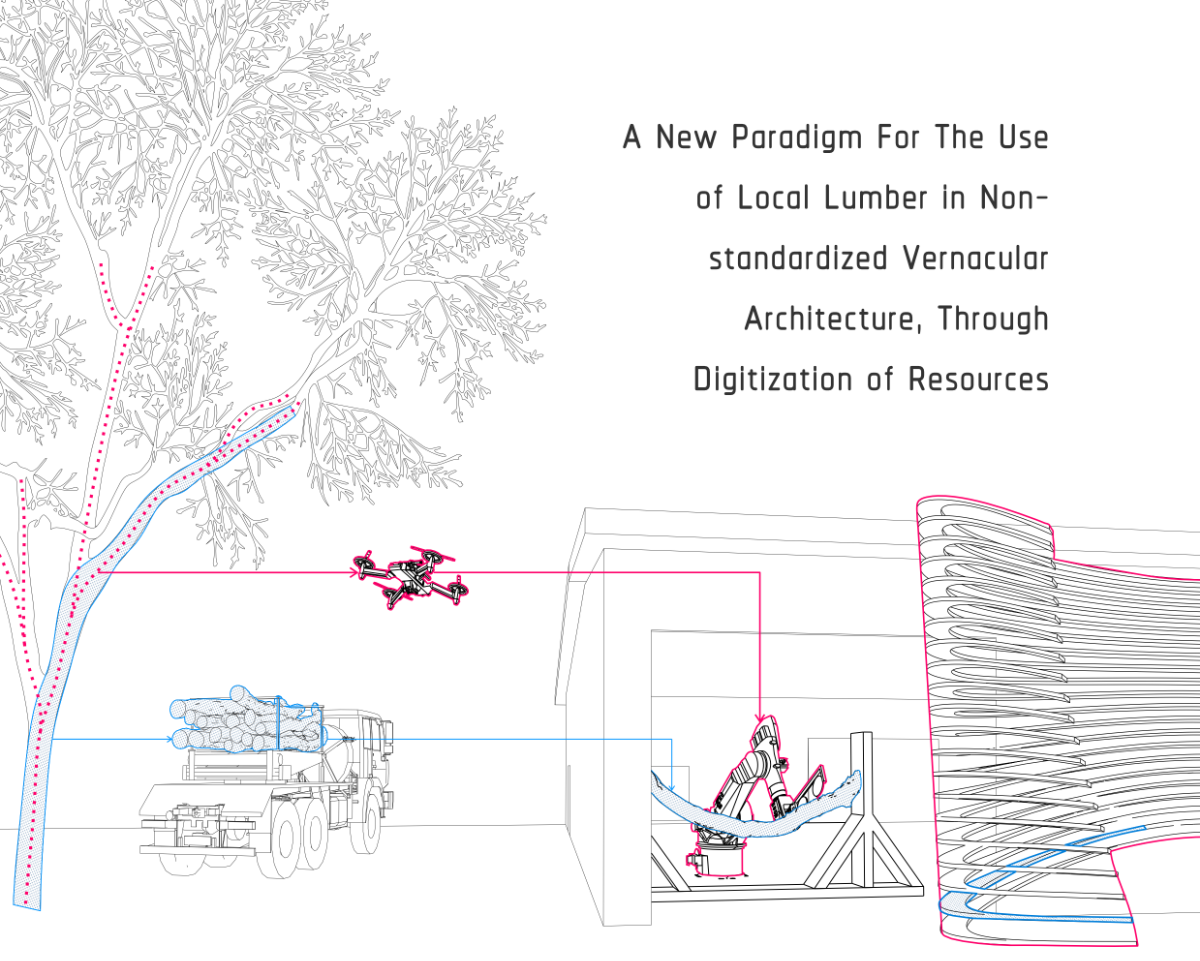
Emerging technologies such as computational design tools, mobile robots and 3d-scanning open up possibilities for the digitization of material resources, allowing more efficient use of materials. Robotic and digital fabrication methods show the possibilities of exploring non-standardized workflows in an industrialized environment.

The following research explores alternative methods to engineered wood processes, intending to use locally sourced timber, and reducing the overall waste in engineered wood processes through integrating material resources and fabrication methods in the early design process.
Areal photogrammetry
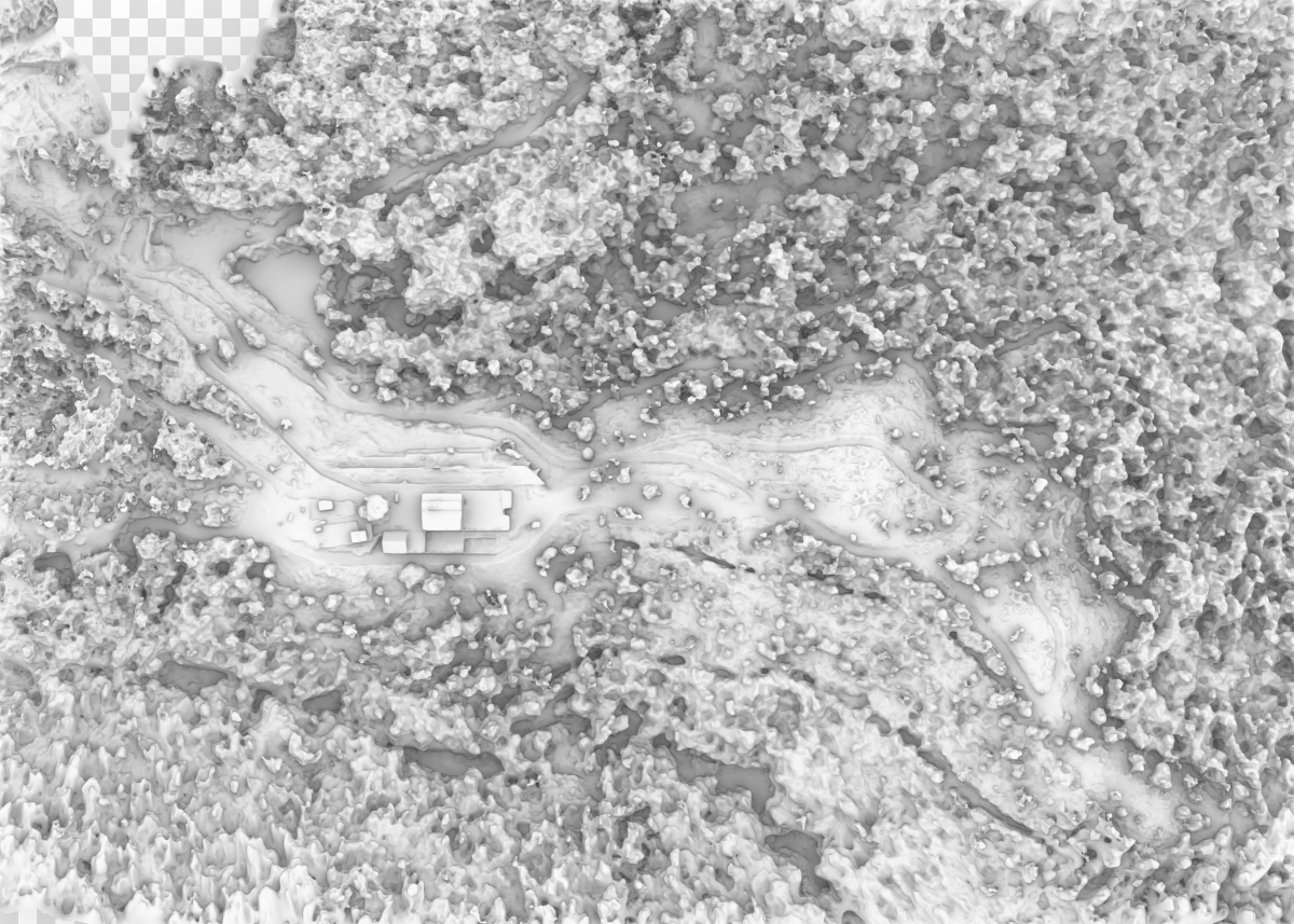
Aerial Scanning of the forest using drones is part of the early processes in digitizing the forest, these models represent data about the position and density of the trees, canopy size, creating topography maps for the forest, finding the trails, estimating water flow patterns etc. This information is useful for forestry and yield estimation purposes.

Sub-canopy navigation and mapping
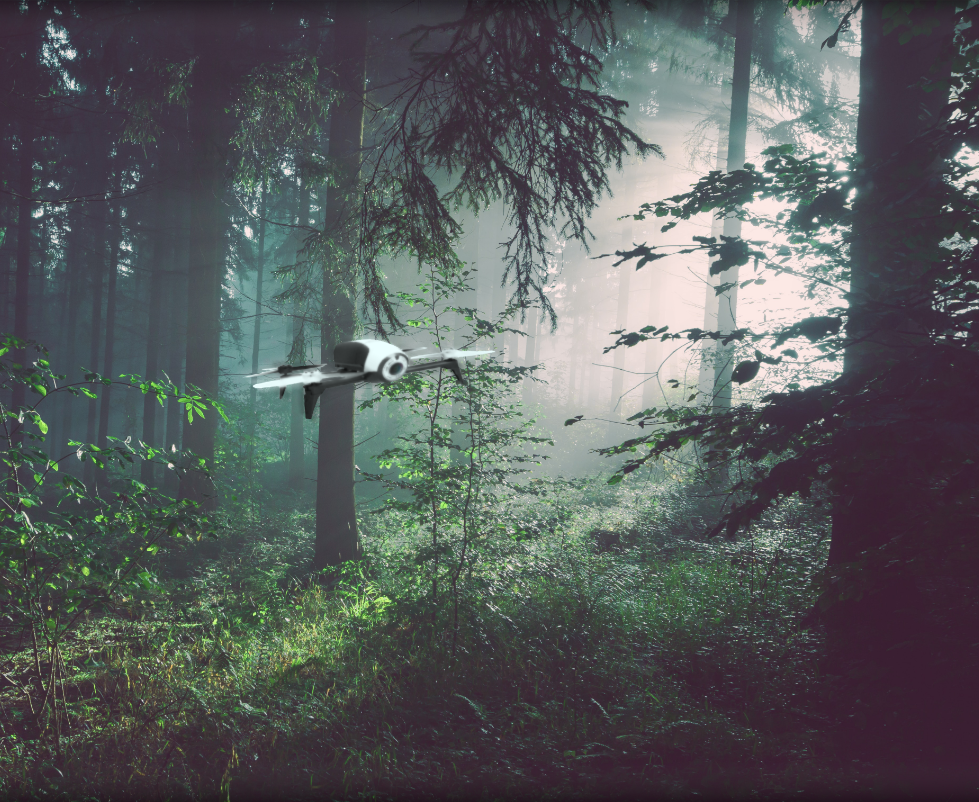
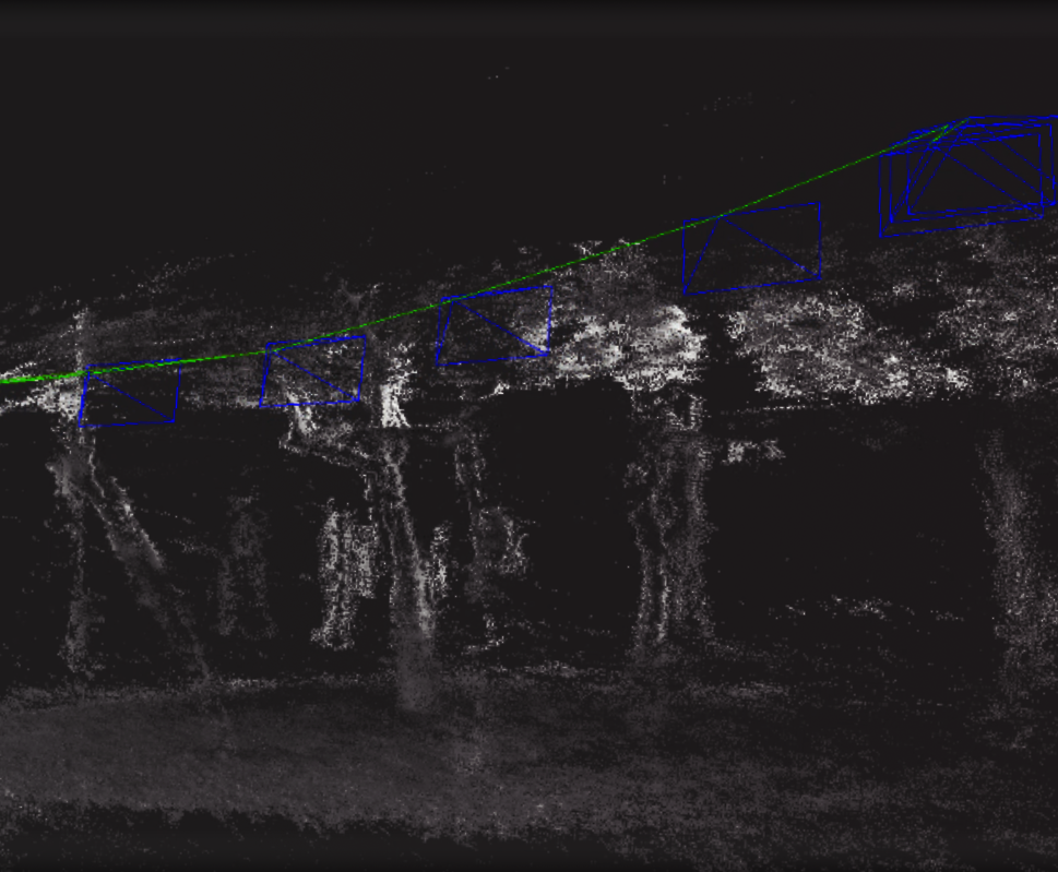
Tree geometry is an important parameter required to quantify timber resources and is essential in evaluating the economic and ecological value of a forest stand. Our research interest lies in building a database from geometries of trees in the forest. Drones flying under the canopy would collect the photos required to apply for photogrammetry method to create a 3d representation of the forest. We have looked into different approaches to localisation in a forest, including state of the art simultaneous localisation and mapping (SLAM) algorithms and computer vision algorithm to detect 2d layouts of trees in the forest as the drone is flying.


Pid Controller For The Drone
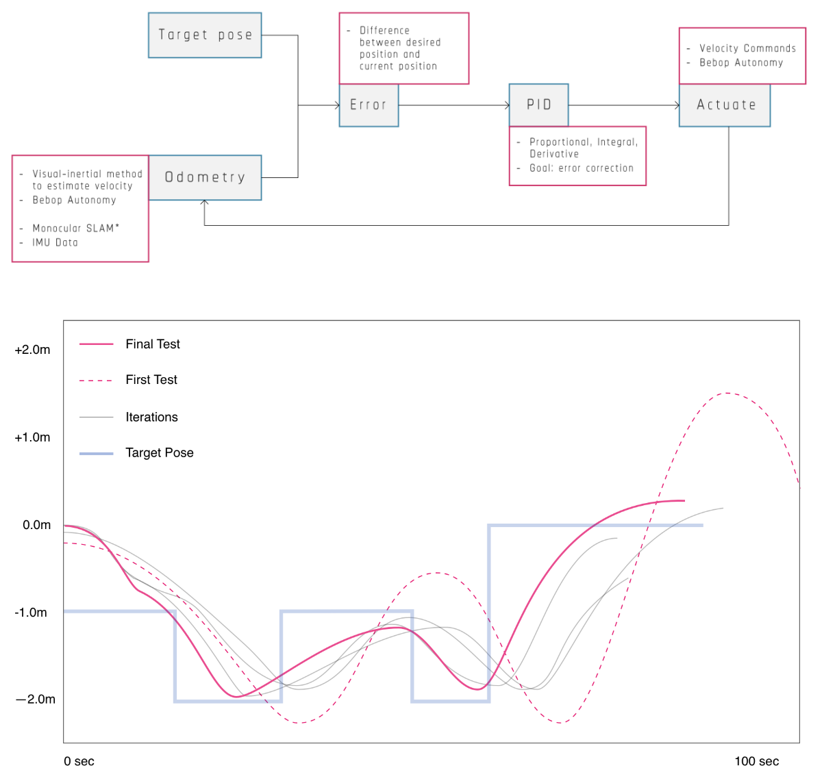
The research introduces a PID Controller for autonomous drone navigation. The workflow is developed around ROS Kinetic for Ubuntu 16.04 (Xenial) and Grasshopper visual scripting language for Rhino3D. The current pose of the drone is read by the controller program from topics published by the Bebop Autonomy driver which contains two vectors: position, and orientation; and compares them with the target pose information that is received from Rhino/Grasshopper. The difference between the current and the target pose is the error. The PID controller attempts to minimize the error over time through adjustment of velocity commands for the drone. When the error is reduced to a predefined threshold, the target pose is updated and the drone moves towards the next target pose.

Point cloud creation
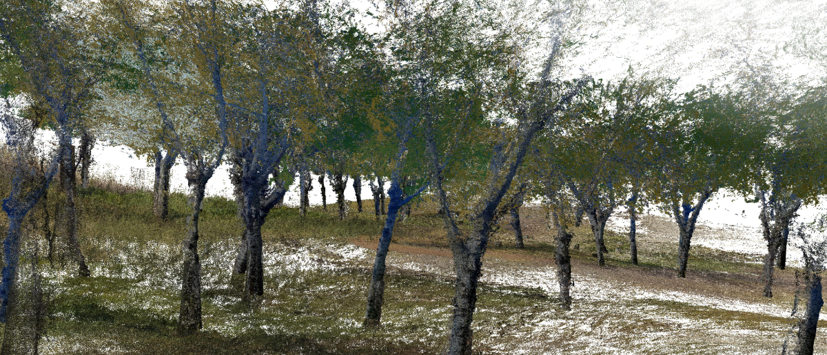
The point clouds are developed in photogrammetry software from the photos captured by drones. Before any specific data can be extracted from them, the point clouds need to be processed. Several processes, such as noise filtering and segmentation, are applied to the raw point clouds.

Cloud segmentation
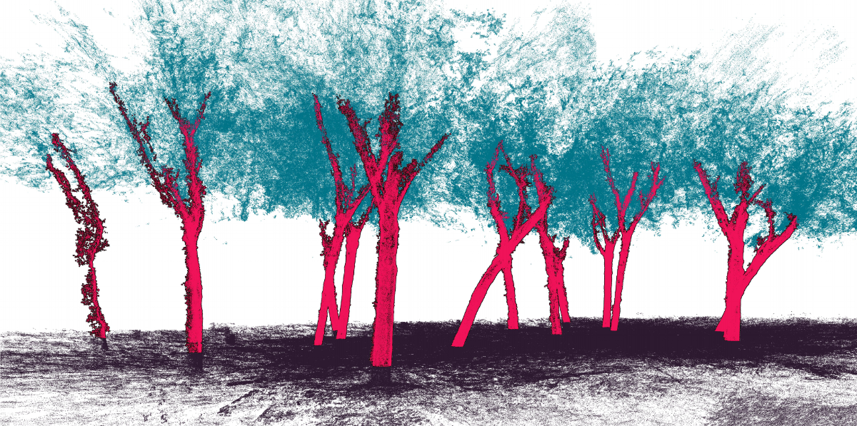
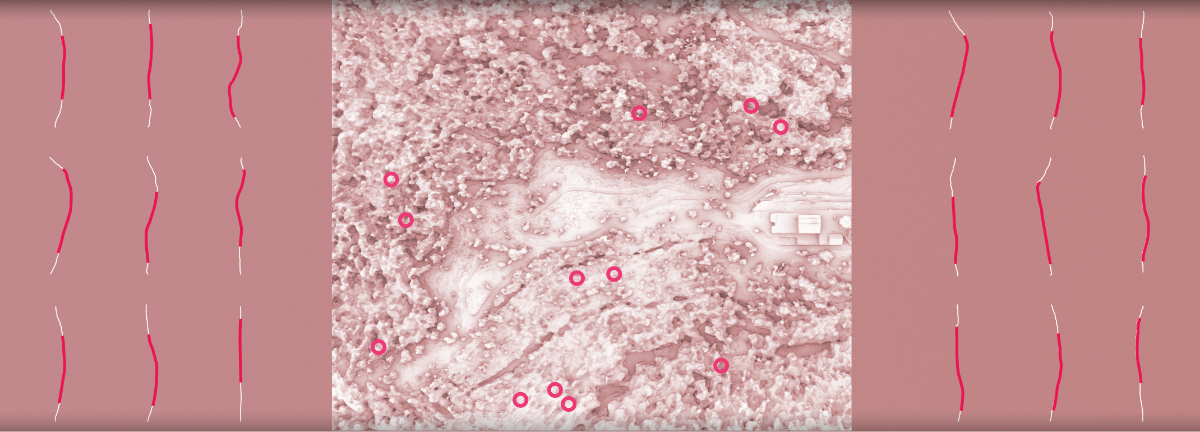
Segmentation algorithms are used to cluster different parts of the point cloud together: ground, trunk, leaves, etc. This process allows us to access each of these clusters separately, which in effect enables the measurements of different types of data in the forest. Tree Trunks are our main interest in creating a database.

Cloud filltering
Segmentation algorithms are used to cluster different parts of the point cloud together: ground, trunk, leaves, etc. This process allows us to access each of these clusters separately, which in effect enables the measurements of different types of data in the forest. Tree Trunks are our main interest in creating a database.

Data extraction
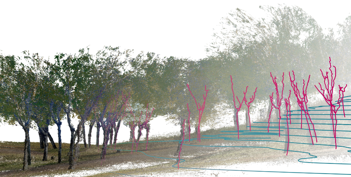
In addition to the tree geometry, topography data can be extracted from forest point clouds, providing exact information about trails, prediction of water flows, sub-canopy vegetation, etc.

The greenest database
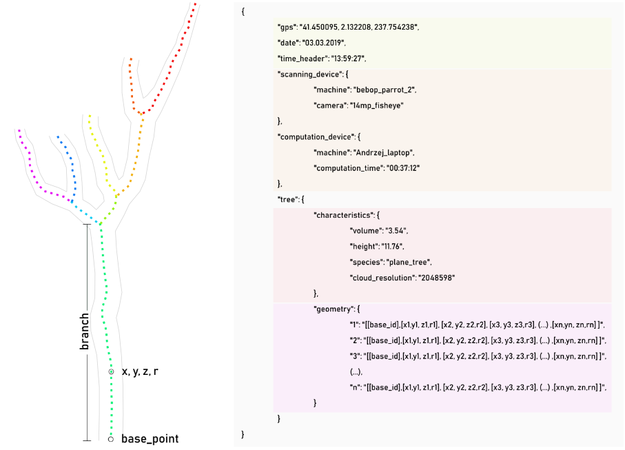
Due to the amount of information in the forest, the database needs to be as lightweight and easy to process as possible. The point clouds are neither. After processing, each tree is represented as a collection of skeletal curves with thickness and connection information embedded.

Tree sorting
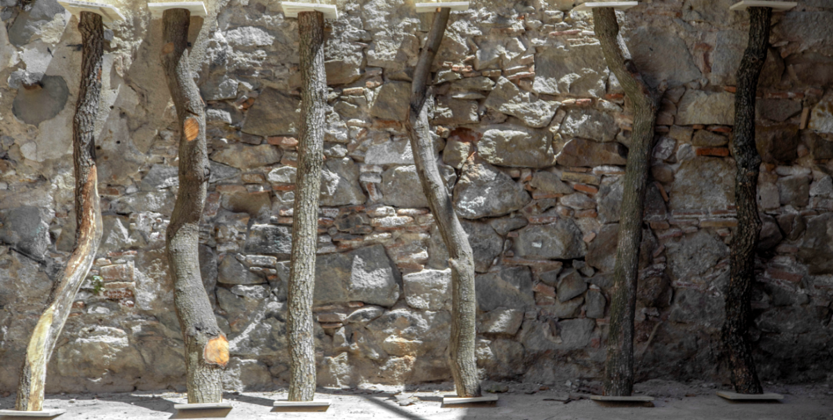
For each branch, the geometry goes through an analysis process. One way to sort these geometries is through curvature. Deviation of the axis line from a straight line that fits through geometry is calculated. This process enables us to sort geometries based on their curvature.

Curve matching
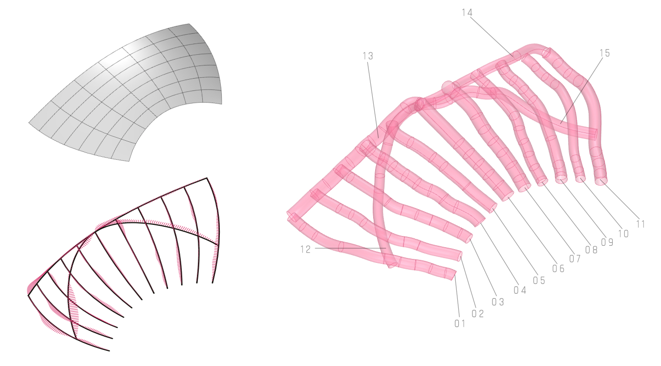
The designed geometry is compared with the skeleton lines of existing branches in our database. In the process, the curves are compared and their deviation from each other is calculated. The search algorithm in this process is searching for the minimum amount of deviation. As each tree in the atabase can only be matched with one curve in the design, a genetic algorithm is optimizing for the lowest overall deviation.

Case study
The designed geometry is compared with the skeleton lines of existing branches in our database. In the process, the curves are compared and their deviation from each other is calculated. The search algorithm in this process is searching for the minimum amount of deviation. As each tree in the atabase can only be matched with one curve in the design, a genetic algorithm is optimizing for the lowest overall deviation.

Curved wood cutting
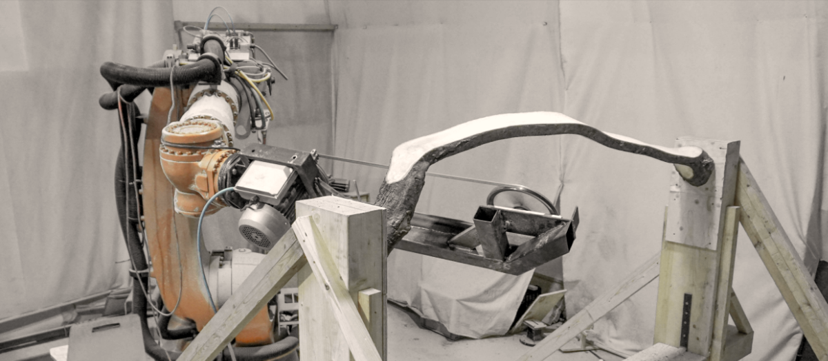
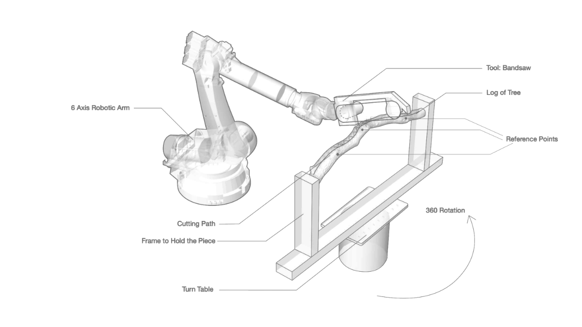
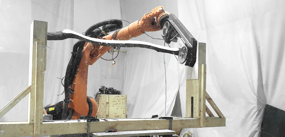
The robotic setup includes a Kuka KR 150 utilized with a bandsaw. The tree log is mounted on a frame attached to the turntable, which acts as a 7th axis for better reachability. To calibrate the piece for the robotic process, we use 3 reference points from the scan of the log. Those points are manually read from the robot tool and the 3d model is adjusted based on that. The cutting path is created from the axis line of the log, following the curvature of the tree.

Fabrication
Each piece is 3d scanned using photogrammetry method to understand the geometry and curvature of the piece.

Cutting path is based on a skeleton line of the branch, which enables us to cut along the curvature and grain direction of the piece, thus enhancing the structural performance of the extracted members.

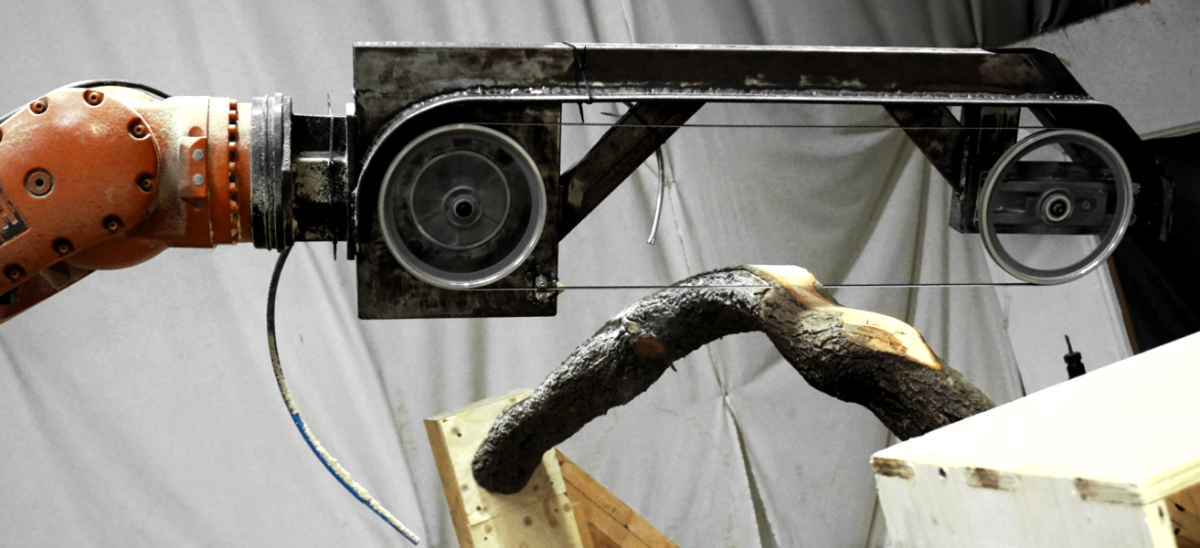
We developed a bandsaw with a resaw capacity of 45cm to be used as the end effector on the robotic arm.

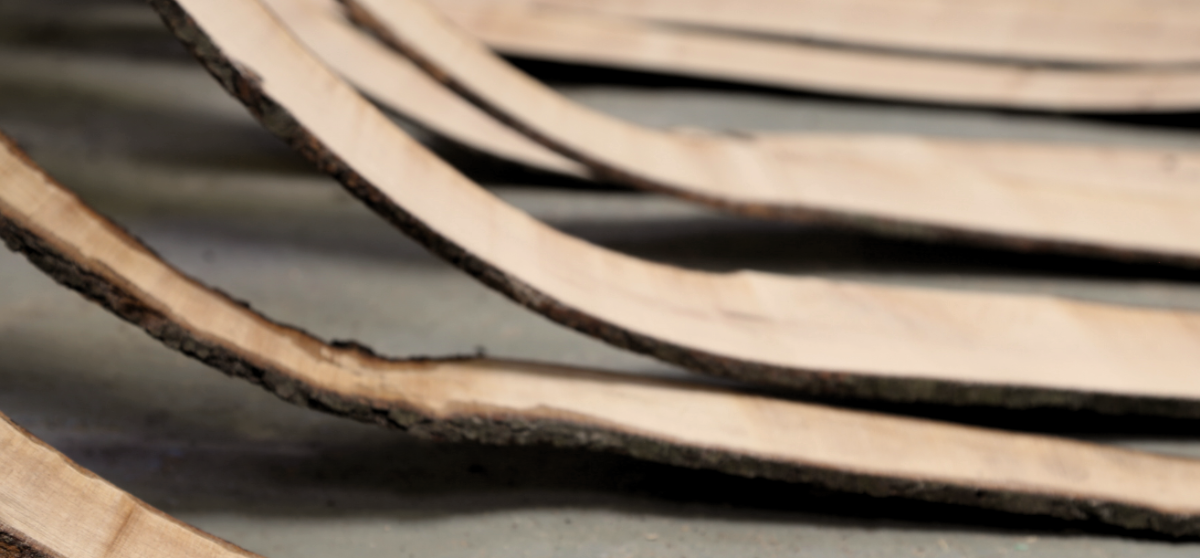
Within 3 days of cutting with our robotic bandsaw, we were able to extract approximately 30 slices with the thickness of 6mm. As the cuts had been done on both sides of the branch, the core of each branch was preserved as well.

Proof of concept
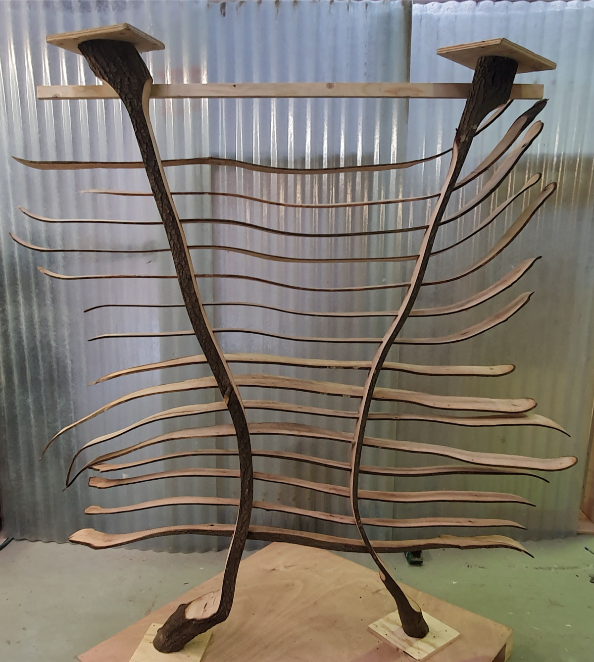
From cut pieces, the shading system panel has been fabricated. In the design process, we have used a bottom-up approach, where horizontal pieces were sorted through the curvature to create the most uniform surface.

